 EN
EN

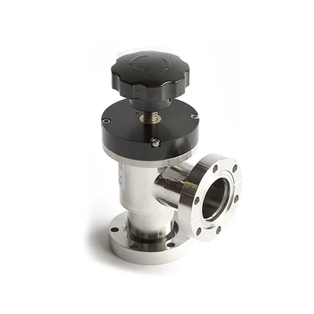
Achieving and maintaining ultra high vacuum conditions is one of the most demanding challenges in precision engineering, scientific research, and advanced manufacturing. Even the smallest leak path or outgassing source can compromise system integrity, making every component in the vacuum assembly a critical variable. Among all the hardware choices available to vacuum engineers, the cf flange stands out as the gold standard for sealing performance in ultra high vacuum environments, and understanding how it contributes to system stability is essential for anyone designing or maintaining such systems.
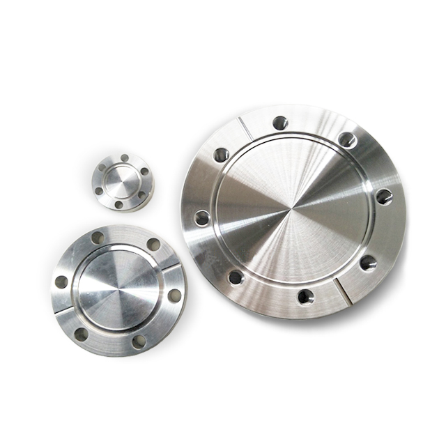
The cf flange, short for ConFlat flange, was engineered specifically to meet the rigorous demands of ultra high vacuum and extreme high vacuum applications. Its knife-edge sealing mechanism, combined with a soft metal gasket, creates a hermetic seal that outperforms virtually every other flange type at pressures below 10⁻⁹ Torr. This article explores the specific ways in which cf flange components contribute to vacuum stability, from their mechanical design principles to their material properties, installation practices, and long-term reliability in demanding industrial and research settings.
The Mechanical Design Principles Behind CF Flange Sealing
Knife-Edge Geometry and Metal Gasket Interaction
The defining feature of the cf flange is its precision-machined knife-edge geometry. When two cf flange faces are bolted together with a soft metal gasket placed between them, the knife edges bite into the gasket material and create a cold-weld seal. This process displaces the gasket metal laterally, filling microscopic surface irregularities and forming a continuous, leak-free barrier. The result is a seal that does not rely on elastomers or polymer compounds, which are known to permeate gases and degrade under thermal cycling.
The geometry of the knife edge is tightly controlled during manufacturing. The angle, sharpness, and concentricity of the edge determine how uniformly the gasket deforms under bolt load. A well-machined cf flange distributes clamping force evenly around the entire sealing circumference, preventing localized stress concentrations that could lead to micro-leaks. This precision is what allows the cf flange to achieve helium leak rates as low as 10⁻¹¹ mbar·L/s under proper assembly conditions.
Because the seal is formed through plastic deformation of the gasket rather than compression of a soft seal, the cf flange maintains its integrity even when subjected to bakeout temperatures exceeding 450°C. This thermal stability is critical for ultra high vacuum systems that require high-temperature baking to drive off adsorbed gases from chamber walls and internal surfaces.
Bolt Pattern and Load Distribution
The bolt pattern on a cf flange is not arbitrary. The number and spacing of bolts are calculated to ensure that the knife-edge load remains consistent around the full sealing perimeter. Uneven bolt torque is one of the most common causes of cf flange seal failure, and the design of the flange itself helps mitigate this risk by providing a rigid, flat mating surface that resists warping under load.
Proper torque sequencing during assembly is essential. Engineers typically follow a star or cross pattern when tightening cf flange bolts, gradually increasing torque in multiple passes to achieve uniform gasket deformation. This approach prevents the flange faces from tilting relative to each other, which would result in an asymmetric seal and potential leak paths on the undertightened side.
The rigidity of the cf flange body also plays a role in load distribution. Flanges machined from stainless steel with sufficient wall thickness resist deflection under bolt load, ensuring that the knife edges remain coplanar throughout the tightening process. This structural integrity is a key reason why the cf flange continues to be the preferred choice for ultra high vacuum connections in particle accelerators, semiconductor fabrication tools, and surface science instruments.
Material Selection and Outgassing Behavior
Stainless Steel as the Primary Flange Material
The cf flange is most commonly manufactured from 304L or 316L stainless steel, both of which offer a favorable combination of mechanical strength, corrosion resistance, and low outgassing rates. The low carbon content of these alloys reduces the risk of carbide precipitation during welding and bakeout, which could otherwise create grain boundary pathways for gas permeation. For ultra high vacuum applications, the surface finish of the cf flange body is also important, as rough or contaminated surfaces can trap gases that slowly desorb into the vacuum chamber.
Electropolishing is frequently applied to cf flange components intended for ultra high vacuum service. This electrochemical surface treatment removes the outermost layer of metal, smoothing microscopic peaks and valleys that would otherwise harbor adsorbed water vapor and hydrocarbons. An electropolished cf flange can achieve significantly lower outgassing rates compared to a mechanically polished equivalent, contributing directly to faster pump-down times and more stable base pressures.
In specialized applications involving strong magnetic fields or corrosive process gases, cf flange components may be fabricated from non-magnetic stainless steel grades or nickel alloys. These material variants preserve the sealing geometry and dimensional standards of the standard cf flange while adapting to the specific environmental constraints of the application.
Gasket Material and Its Role in Vacuum Stability
The gasket used with a cf flange is as important as the flange itself. Oxygen-free high-conductivity copper is the most widely used gasket material for standard ultra high vacuum applications. OFHC copper is soft enough to deform readily under knife-edge load, yet strong enough to maintain the seal under thermal cycling and mechanical vibration. Its extremely low outgassing rate and negligible vapor pressure at elevated temperatures make it ideal for baked ultra high vacuum systems.
For applications requiring repeated assembly and disassembly, aluminum gaskets are sometimes used with cf flange connections. Aluminum is softer than copper and deforms more easily, which can be advantageous when flange surfaces show minor wear from previous assemblies. However, aluminum gaskets are generally not recommended for systems that will be baked above 150°C, as the material can anneal and lose its sealing force at higher temperatures.
Indium gaskets represent another option for cf flange sealing in cryogenic applications. Indium remains ductile at very low temperatures where copper and aluminum would become brittle, making it the preferred choice for cf flange connections on cryostats and low-temperature experimental chambers. Selecting the correct gasket material for the specific thermal and chemical environment is a critical step in optimizing cf flange performance and long-term vacuum stability.
How CF Flange Components Prevent Leak Paths in Complex Systems
Blank Flanges and System Termination
In any ultra high vacuum system, unused ports must be sealed reliably to prevent atmospheric ingress. The cf flange blank, also known as a blind flange, is a solid disk machined to the same dimensional standards as a standard cf flange, complete with the knife-edge sealing geometry on one face. When bolted to an open cf flange port with an appropriate gasket, the blank flange creates a hermetic termination that contributes zero virtual leak volume to the system.
The use of a properly installed cf flange blank is far superior to temporary plugs or cap fittings that rely on thread seals or O-rings. Because the blank flange uses the same knife-edge metal gasket seal as every other cf flange connection in the system, it provides consistent, predictable leak performance that can be verified by helium leak detection. This uniformity simplifies system qualification and troubleshooting.
Blank flanges are also used during system construction to protect open ports from contamination while other assembly work is in progress. A cf flange blank installed on a clean, capped port prevents dust, moisture, and hydrocarbons from entering the vacuum envelope, reducing the conditioning time required to reach base pressure after the system is fully assembled and sealed.
Reducing Virtual Leaks Through Proper CF Flange Assembly
Virtual leaks are a persistent challenge in ultra high vacuum systems. They occur when trapped volumes of gas, typically enclosed between a gasket and a flange face or within a blind tapped hole, slowly desorb into the vacuum chamber after the system is pumped down. The cf flange design minimizes virtual leak risk through its open, through-hole bolt pattern and the predictable deformation behavior of the metal gasket.
When assembling a cf flange connection, cleanliness is paramount. Any contamination on the knife-edge surfaces or gasket faces can prevent complete sealing and introduce outgassing sources. Standard practice involves cleaning all cf flange components with appropriate solvents, handling them with lint-free gloves, and inspecting the knife edges under magnification for nicks or scratches before assembly. A single scratch across the knife edge of a cf flange can create a leak path that no amount of additional bolt torque will eliminate.
The torque values specified for cf flange assemblies are not arbitrary safety margins. They are calculated to achieve the precise gasket deformation needed for a reliable seal without overloading the knife edges or stretching the bolts beyond their elastic limit. Following the manufacturer's torque specifications and using calibrated torque wrenches is a straightforward practice that has a direct and measurable impact on cf flange seal reliability and overall vacuum system stability.
Long-Term Reliability and Maintenance Considerations
Bakeout Compatibility and Thermal Cycling Performance
One of the most significant advantages of the cf flange over alternative sealing technologies is its compatibility with high-temperature bakeout procedures. Ultra high vacuum systems routinely require baking at temperatures between 150°C and 450°C to accelerate the desorption of water vapor and other gases from internal surfaces. During bakeout, the entire vacuum assembly, including all cf flange connections, is heated uniformly and then allowed to cool slowly.
The all-metal construction of the cf flange seal means that it expands and contracts with the surrounding hardware during thermal cycling without losing its sealing integrity. The copper gasket, once deformed by the knife edges, maintains its seal geometry through repeated thermal cycles because the plastic deformation that created the seal is not reversed by temperature changes within the normal bakeout range. This behavior is fundamentally different from elastomer-sealed flanges, where the seal material can creep, harden, or outgas during thermal cycling.
For systems that undergo frequent bakeout cycles, it is good practice to inspect cf flange connections periodically for signs of gasket extrusion or bolt relaxation. While a properly assembled cf flange connection is highly stable, the cumulative effect of many thermal cycles can gradually reduce bolt preload, particularly if the bolts were not torqued to the correct specification initially. Periodic retorquing after the first few bakeout cycles is a common maintenance practice that helps preserve long-term cf flange seal performance.
Inspection, Replacement, and System Longevity
The cf flange is designed for reliable, long-term service, but it is not immune to wear. The knife-edge geometry is the most vulnerable feature of the flange, and any mechanical damage to the knife edge will compromise sealing performance. Regular visual inspection of cf flange faces during system maintenance is an important practice, particularly for flanges that are frequently assembled and disassembled.
Gaskets used in cf flange connections are single-use components. Once a copper or aluminum gasket has been deformed by the knife edges, it cannot be reused reliably. Attempting to reuse a cf flange gasket is a common source of vacuum leaks in research and industrial settings. Maintaining an adequate stock of correctly sized gaskets and replacing them every time a cf flange connection is broken is a basic but essential maintenance discipline.
When a cf flange body shows signs of knife-edge damage, such as nicks, scratches, or corrosion pitting, the flange should be replaced rather than repaired. Attempting to re-machine a damaged knife edge in the field rarely produces results that meet the dimensional tolerances required for reliable ultra high vacuum sealing. Investing in replacement cf flange components is far more cost-effective than the downtime and diagnostic effort associated with a persistent vacuum leak.
FAQ
What makes the cf flange more suitable for ultra high vacuum than other flange types?
The cf flange uses a metal-to-metal knife-edge seal with a soft metal gasket, which eliminates the gas permeation and outgassing problems associated with elastomer-sealed flanges. This all-metal construction allows the cf flange to achieve leak rates below 10⁻¹¹ mbar·L/s and to withstand bakeout temperatures above 400°C, both of which are essential requirements for ultra high vacuum systems operating below 10⁻⁹ Torr.
Can a cf flange connection be reused after disassembly?
The cf flange body itself can be reused many times provided the knife-edge geometry remains undamaged. However, the gasket must always be replaced with a new one after each disassembly. Reusing a deformed gasket is a leading cause of cf flange leaks and should be avoided regardless of how minor the previous assembly appeared to be.
How does a blank cf flange contribute to overall vacuum system stability?
A blank cf flange seals unused ports using the same knife-edge metal gasket mechanism as all other cf flange connections in the system. This provides hermetic, bakeout-compatible termination of open ports without introducing virtual leak volumes or outgassing sources. It also protects open ports from contamination during system assembly and maintenance, reducing conditioning time and improving base pressure performance.
What are the most common causes of cf flange seal failure in ultra high vacuum systems?
The most frequent causes of cf flange seal failure include improper bolt torque or uneven torque sequencing, reuse of previously deformed gaskets, contamination of the knife-edge or gasket surfaces during assembly, and mechanical damage to the knife-edge geometry from mishandling or tool contact. Following established assembly procedures, using calibrated torque tools, and handling cf flange components with appropriate care eliminates the vast majority of these failure modes.
Table of Contents
- The Mechanical Design Principles Behind CF Flange Sealing
- Material Selection and Outgassing Behavior
- How CF Flange Components Prevent Leak Paths in Complex Systems
- Long-Term Reliability and Maintenance Considerations
-
FAQ
- What makes the cf flange more suitable for ultra high vacuum than other flange types?
- Can a cf flange connection be reused after disassembly?
- How does a blank cf flange contribute to overall vacuum system stability?
- What are the most common causes of cf flange seal failure in ultra high vacuum systems?